
By the early twentieth century one of the problems the British had with their heavy naval guns was that existing gun machinery could not elevate or depress the guns quickly enough to compensate for the roll of the ship. In some conditions the turntables could not rotate fast enough to keep the guns bearing on the target.
This stood against the principles of continuous aim, which had been developed by Percy Scott from 1899 and which he had successfully applied to smaller weapons. As ranges increased, the issue of elevation rates, in particular, became problematic. The only answer was for the gun-layer to wait for the roll to bring the guns to the angle indicated by the fire-control solution.[1] But that reduced the rate of fire and, in any case, stood against the continuous-aim principle. By holding the gun on the elevation required to hit the target – irrespective of roll – rates of fire could, at least on paper, approach a maximum theoretical figure once a fire-control solution had been achieved.
By 1904 Captain John Jellicoe, as Director of Naval Ordnance, was determined to rectify the problem. New-design machinery for mounting, protecting, feeding and pointing the guns was implicit in the development of the new Mk X 45-calibre 12-inch gun ordered in 1903. The result was the B.VIII gun machinery, designed by Vickers.[2]
Specifications of B.VIII gun machinery
The key specifications for the B.VIII, described in a confidential Admiralty paper as ‘hydraulic gun machinery’[3] – were sufficient rate-of-change of elevation and speed of rotation to be able to continuously track a target; ability to load at any angle of elevation or angle of training when under power; ability to be worked manually (unpowered) at a fixed angle of elevation; ability to stop both mounting rotation and gun elevation accurately without overshooting; and ability to hold any training angle without slipping.[4]
The resulting particulars of the B.VIII and the modified B.VIII* have been variously stated in secondary literature,[5] and actual figures also varied by minor values between particular mountings built for service, as revealed in specific ship reports. These last discrepancies reflected the difficulty of building heavy machinery to the precision required.[6] In general, the system was designed to independently elevate two Mk X 12-inch/45 calibre guns to maximum angles between stops of +13.5 and -5 degrees,[7] and to be able to load them at any of these angles. Maximum elevation was sufficient to allow a 2 crh shell to range to about 16,450 yards on paper, and a 4 crh shell to about 18,850 yards.[8] Practical ranges available from the gun machinery and gun in reasonable sea states, as recorded aboard HMS New Zealand at Jutland (as one example) differed somewhat.[9] This underscored the point that various numbers given in differing secondary publications, such as range, are indicative rather than actual real-world figures. After Jutland some of the installations were modified to increase elevation to 16 degrees.
The engineering challenge for designers lay in the scale, coupled with the required precision. This machinery had to move 12-inch gun barrels that weighed over 58 tons each, with breech,[10] at required speed, and to accuracies measured in arc-seconds. They had to maintain that accuracy reliably for years, despite the rigours of service, including the shock of repeatedly firing weapons which required propellant charges of up to 258 lb of cordite.[11] The formal specification explicitly demanded that ‘Particular attention is to be paid to careful fitting of all plates and joints subject to stresses set up on firing or recoil’.[12] The guns, the turntables, the hydraulic apparatus and the gun-house had to be built to tolerances that maintained a ‘vertical clearance of not less than .5 inch’ between ‘the machinery and all parts of the fixed supports and other portions of the ship.’[13] Gun-house rollers – whose pins were equipped with phosphor-bronze bushes, ‘forced in with hydraulic pressure’ were required to be within 0.002-inch of ‘the plan dimension’.[14] All of it had to be balanced: despite the fact that the guns protruded asymmetrically from the front of the gun-house, the ‘centre of gravity of the revolving structure’ had to be ‘not more than 4 inches to the front of the centre of rotation’.[15] All this pushed the limit of what period engineering could achieve.
The general design reflected the steady evolution of British heavy naval gun machinery since the 1880s. The original concept of the barbette mounting, with its rotating platform, working room beneath and ‘trunk’ leading down to the magazines and shell rooms, remained at the centre of the system. However, the detail had radically developed from open-topped barbettes into barbettes with armoured gun-houses, later called ‘turrets’. Mechanical workings had also steadily evolved over the years. Early British barbette-based gun machinery could load only at a fixed angle of elevation and training. But later versions introduced all-round loading. The B. VIII system extended this still further and – in line with that heritage – comprised several major components in addition to the slides, trunnions and hydraulics supporting the guns.
These components were subdivided in the commissioning contracts into specific groups, largely to permit incremental payment during construction, consisting of:
- Turntables, loading chambers, trunks and other elements of the revolving structure.
- Turning gear, engines, gearing and detail fittings, including training engines, worm shaft and bearing brackets, clutch gears, training control gear and indicator gear among other apparatus.
- Gun mountings, including slides, loading arms, carriages, loading chambers, sighting stools and ‘gun clearing apparatus’. It also encompassed the trunnion gear, elevating cylinders ‘complete with rams, crossheads, connecting links, covers, glands, and all details’.
- Steam pumping engines, ‘and all fittings in connection herewith’, such as the ‘walking pipes’ that allowed hydraulic pressure to be brought to the revolving gun-house.
- Hydraulic exhaust pipes in the revolving structure, walking pipes, stop valves and other fittings.
- Shell-room machinery, including ‘hand-lifting and traversing winches’, hydraulic traversing equipment, shell grabs and overhead rails.
- Hoists, including gun-loading hoist cages, cut-off gear, cordite waiting tray, hand-loading trays, telescopic rammers in the working chamber and more.
- Hydraulic pressure and exhaust values and fittings outside the revolving structure, including heating equipment.
- Rails, guards, and ‘all fittings not included in other groups’, such as voice pipes and navyphones among other miscellaneous gear.
- ‘Shield structures’ – essentially, the armoured front, roof, sides and back of the gun-house, including ‘sighting hoods with blast screens’.
- Models and drawings. These drawings were owned by the Admiralty and provided to the manufacturers. They were expensive to produce.[16]
Each set of gun machinery was built, piece by piece, in ‘erecting pits’ – shafts dug below floor-level in Britain’s major naval ordnance plants, into which these mountings were constructed. With armour and guns in place a typical B.VIII* mounting topped 430 tons weight in battlecruiser use, more for dreadnoughts where gun-house side and face armour was heavier.
Cost and manufacture of the B.VIII and its variants
In 1904 just two companies in Britain were able to make heavy gun machinery: the Vickers, Sons & Maxim conglomerate (‘Vickers Ltd’ after 1911),[17] and the Elswick Ordnance Company owned by W. G. Armstrong Whitworth & Co Ltd.[18] Each set was individually built to order, and there were minor variances between them, in part due to where they were to be located in any given ship, but also because they were individually built, and many small construction details – such as lights for the operating crew – could vary.
None of this was cheap. The two B.VIII mountings built for Dreadnought by Vickers, for instance, came in at £69,860 each.[19] By 1910, that had come down to the £51,898 each that Elswick and Vickers competitively tendered for a job lot of eight B.VIII mountings ordered by the Admiralty for HMS New Zealand and HMAS Australia, which they intended to split four each between the two companies.
This figure included itemised components such as turntables, training gear, slides, pumping engines, pressure and exhaust pipes, shell room machinery, transporting gear, external pipes, brackets and rails, shield structure, shield armour, drawings and models, and spare mounting (the physical structure connecting the slide to the rest of the mount) and front armour.[20] However, it did not include delivery costs of up to £5,430, or what the quote called ‘erection costs’ – reassembling the mounting in the intended ship, for which the cheapest price from Elswick was £14,035 if the ship happened to be built nearby in the Elswick yard, but up to £23,480 if it was being built on the Thames. Other costs included £1,120 to supply ‘drawings, jigs and gauges’ to Vickers; a £4 daily charge for ‘preservation and maintenance’, and £300 to paint them – also itemised separately.[21]
Quotes of this kind did not include ancilliary gear. As one example, obdurator nozzles for the wash-out squirts were charged separately and often bought in bulk, as in May 1910 when a batch was procured from Armstrong-Whitworth & Co for HMS Lion, Monarch and New Zealand, cutting the price to £1.7.6 each.[22] Similarly, adapter tubes for drill telescopes, among other gear, were separately purchased from manufacturers such as W. Ottway & Co – in their case for about £1.14 each.[23]
These figures underscore the fact that naval hardware of the day was a fortune in period money.[24] Just how expensive is difficult to express in modern terms. By direct consumers’ price index values the Dreadnought B.VIII gun machinery figure translates to £5,930,784 each in 2021 values (the latest available at time of writing),[25] however a CPI comparison is misleading because it is an average of a ‘basket’ of goods and does not reflect changes in specific classes of product. (A paper I wrote for a peer-reviewed journal on historical CPI calculation is here: https://www.rbnz.govt.nz/hub/publications/bulletin/2003/rbb2003-66-04-03). A more useful impression of the cost in human terms of the day can be gained from the fact that in the United Kingdom, average annual per-capita income was just over £42.[26] In short, even at the bulk-buy price, a single obdurator nozzle for the wash-out gear equated to more than an average week’s income at the time.
These prices also only covered the gun machinery. The actual Mk X 12-inch guns fitted into each B.VIII were charged separately and were of enormous cost themselves. As example, the 22 Mk X 12-inch guns ordered in March 1910 as a combined set for HMS New Zealand and HMAS Australia – eight guns per ship plus three spares each, on standard Admiralty practise of a 40-percent spare reserve per ship – came to £220,990 all up, even as a job lot.[27] But again, there were other costs – this price did not include proof firing and checks, spare parts, or ammunition (at the time, the cost of the first load of ammunition was typically considered part of the purchase cost of the ship).[28]
Service development of the B.VIII
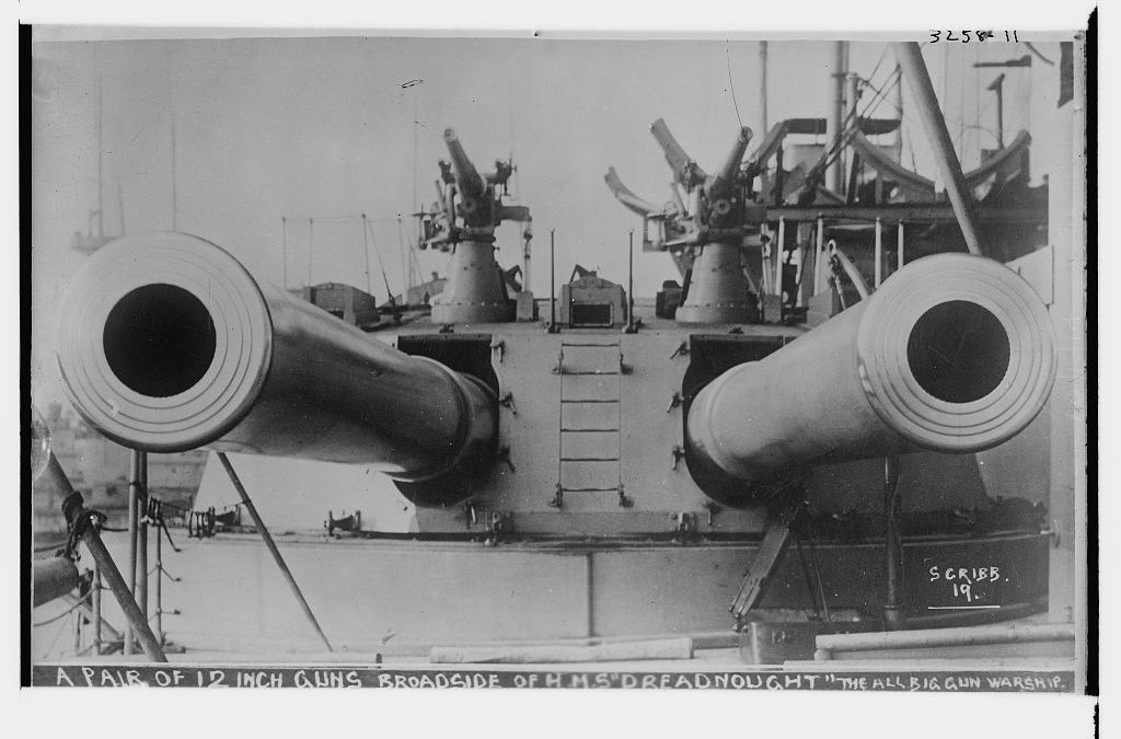
The B.VIII mounting was initially ordered for the Lord Nelson class battleships of the 1904-05 programme, but in the event went to sea for the first time aboard HMS Dreadnought.[29] As an aside, and despite oft-repeated mythology about this ship using the mountings intended for the Lord Nelsons, it appears that five B.VIII mountings were specifically ordered for Dreadnought in July 1905, and tenders called from Vickers (two) and Elswick (three).[30] It should be noted that when engineering plans were shared between these companies, each copy had to be individually drawn by draftsmen; and each copy – sometimes also provided with builders’ models – usually carried a charge as a result, up to £600.[31] Again, this was an enormous price in everyday human terms of the period.
The initial examples were hydraulically driven with a three-cylinder training engine, powered by connection to the ship’s main hydraulic system and controlled by levers. However, tests aboard Dreadnought showed it still could not achieve continuous aim. Later, elevation and training was controlled by hand-wheels, which broadly corrected the issue of control authority. But the early Dreadnought experience showed that improvements were still needed to the machinery itself.
Experiments were also conducted with electrically-driven mountings fitted to HMS Invincible – which had increased depression of -7 degrees.[32] Although otherwise very similar to the B.VIII, these systems were dubbed B.IX and B.X. However, the B.VIII hydraulic systems were found to be less troublesome. Elswick then added a 7-cylinder swash-plate engine to improve the rate at which the mounting rotated, reaching a rate of around 2 degrees a second. Elevation rates were theoretically up to 3 degrees a second, on paper; but as we will see in the next article, varied with individual construction.
Eventually the design was modified to a new standard, the B.VIII* (with asterisk), denoting a power-operated auxiliary hoist.[33] Further small modifications were made to the gun-house built atop the mounting for HMS Indefatigable and her two sister ships, primarily to alter the design of the gun-shields.[34]
The B.VIII gun machinery and its variants, with 12-inch 45/calibre Mk X guns, was fitted to the following classes: Lord Nelson, Dreadnought, Invincible (except Invincible herself), Bellerophon and Indefatigable.
Next time, we’ll cover an inspection of two B.VIII* mountings in the Elswick erecting pit, giving specific details of the performance of these mountings as recorded at the time, along with the way the actual specifications varied from the paper design.
Meanwhile, check out my book on HMS New Zealand’s political origins and war career, published by Seaforth and USNI Press.
[1] John Brooks, ‘Dreadnought: blunder or stroke of genius?’, War in History, Vol. 14, No, 2, 2007, p. 165
[2] Noted in John Brooks, ‘Fire Control for British Dreadnoughts – Choices of Technology and Supply’, PhD thesis, Department of War Studies, King’s College, London 2001, p. 58.
[3] Archives New Zealand (ANZ) R3485891, ‘Hydraulic gun machinery for 12-inch BL 45-calibre guns’.
[4] See, e.g. ibid.
[5] See, e.g. http://www.navweaps.com/Weapons/WNBR_12-45_mk10.php which lists depression on the naval mounting as -3 degrees; compare with Friedman, Naval Weapons of World War 1, USNI Press, Washington, p. 61 at -5 degrees.
[6] See, e.g. Archives New Zealand, R3485893, ‘Report of pit trial of “P” turret of “New Zealand’ (colonial cruiser) carried out at Elswick, 3rd Novr. [sic] 1911.’
[7] Norman Friedman, Naval Weapons of World War 1, USNI Press, Washington, p. 61. Also compare, e.g. Archives New Zealand, R3485893, ‘Report of pit trial of the 12-inch gun machinery of “X” turret of H. M. Battle Cruiser “New Zealand” at Elswick Ordnance Works, 28 December 1911.
[8] Friedman, Naval Weapons, p. 61.
[9] Matthew Wright, The Battlecruiser New Zealand: A Gift to Empire, Seaforth, Barnsley 2021, p. 169.
[10] Specifically, 127,232 kbs (without breech), 129,348 lbs (with), see http://www.navweaps.com/Weapons/WNBR_12-45_mk10.php
[11] Ibid.
[12] ANZ R3485891, ‘Hydraulic gun machinery for 12-inch BL 45-calibre guns’.
[13] ANZ R3485891, ‘Hydraulic gun machinery for 12-inch BL 45-calibre guns’.
[14] Ibid.
[15] Ibid.
[16] Ibid.
[17] https://www.gracesguide.co.uk/Vickers,_Sons_and_Maxim
[18] See Nicholas A. Lambert, Sir John Fisher’s Naval Revolution, University of South Carolina Press 1999, p. 149.
[19] See, e.g. https://defence.pk/pdf/threads/battleships-h-m-s-dreadnought.302225/
[20] ANZ, R3485891, ‘Statement showing prices tendered for 12-inch mountings’.
[21] ANZ, R3485891, ‘Statement showing prices tendered for 12-inch mountings’.
[22] ANZ, R3485891, extracts from a letter dated 28 May 1910. Currency was pound, shillings and pence at 20 shillings to the pound, 12 pence to the shilling.
[23] ANZ, R3485891, High Commissioner to Prime Minister, ‘Armoured cruiser New Zealand’, 28 July 1911.
[24] See, e.g. ANZ, R3485891, Secretary of the Admiralty to New Zealand High Commissioner, 19 March 1910.
[25] Via https://www.bankofengland.co.uk/monetary-policy/inflation/inflation-calculator
[26] Summarised from census data, see https://www.nationalarchives.gov.uk/pathways/census/events/polecon3.htm
[27] Archives New Zealand, R3485891, Secretary of the Admiralty to New Zealand High Commissioner, 15 March 1910, ‘Statement X’.
[28] Noted in Matthew Wright, The Battlecruiser New Zealand: A Gift to Empire, Seaforth, Barnsley 2021, p. xx.
[29] See, e.g. John Brooks, ‘Dreadnought’ p. 164, compare Norman Friedman, The British Battleship 1906-1946, p. 81.
[30] Noted in https://defence.pk/pdf/threads/battleships-h-m-s-dreadnought.302225/
[31] Archives New Zealand, R3485891, ‘Statement showing prices tendered for 12-inch mountings’.
[32] Noted in Friedman, Naval Weapons, p. 61.
[33] Per Brooks, ‘Fire control for British dreadnoughts’, p. 58, see also Norman Friedman, Naval Weapons of World War One: Guns, Torpedoes, Mines and ASW Weapons, Naval Institute Press, Annapolis, 2011.
[34] Noted in http://www.navweaps.com/Weapons/WNBR_12-45_mk10.php

Recent Comments