
Over the years, I have been asked a great many naval history questions by curious readers. It’s actually quite an honor to have people reach out to me and I love getting to chat to people and answering the questions that I can. Even those that escape me are no problem as I can often point the person in the right direction thanks to the connections that I have made over the years. So long as a question is answered, I consider that a win!
Due to the great many questions I have received, I decided to start compiling all of them into an article.
Facebook Q&A : Warship Stability
“When reading about a warship, it was described as having a long and slow rolling motion. It was also described as being a stable ship. Shouldn’t a stable warship not roll that much?”
**Before I take a crack at answering this question, I want to point out that there are a lot of scientific terms that could be used for this question that I do not know. Instead, I’m going to use my “dumbing down” of the answer to hopefully better describe it to everyone**
I’m going to answer this question by describing two ships:
1- The Stable Warship
2- The Steady Warship
Aren’t those the same things? Not quite. Let’s talk about metacentric height.
Metacentric height is a measurement of a floating object’s initial stability. For the purposes of this post, metacentric height influences two things we need to keep in mind.
– Stability: The higher a ship’s metacentric height, the more stable it wants to be.
– Roll Period: Because a higher metacentric height means greater stability, it also means more resistance to rolling motions. Thus a ship with a higher metacentric height resists rolling, producing a shorter roll period.
**There is a lot more to know about metacentric heights, but this article is trying to dumb it down. So if you want more information, there are plenty of websites discussing metacentric height**
So a high metacentric height is best, right? Stability is good and rolling is bad after all.
Nope! At least, its not that simple. Let’s go back to our two warships.
-The Stable Warship-
Let’s assume our stable warship has a higher metacentric height. This gives our warship ample stability, meaning it does not want to roll at all.
Now, having a lot of stability can be a good thing. A more stable ship wants to stay upright and this includes when it takes on additional weight (cargo, munitions, equipment). This also includes damage as a ship with high stability will retain it longer even when flooded (a higher metacentric height = a higher margin of safety).
However, excessive stability does have its drawbacks. Because the warship is so stable that it wants to resist rolling, it aggressively responds to being pushed off center. Essentially, as soon as the warship rolls in one direction, it quickly and violently pushes itself in the other direction to right itself again.
This results in a very short, very quick rolling motion. This can be a problem for a variety of reasons. For a warship, this rapid motion can cause havoc with fire control, making it harder for rangefinders and directors to operate. It can also throw off the aim of the gunners as the ship unpredictably reacts to rolling motions. This rolling motion can also be extremely uncomfortable for the crew.
-The Steady Warship-
Unlike the other warship, our steady warship has a lower metacentric height. This warship has lower stability and does not want to resist rolling motions as much.
This is not as bad as you might think. Instead of violently resisting any rolling motion, the warship instead goes along with it. The ship will gradually resist the motions and bring itself back upright. This means that it will have a longer, gentler rolling motion.
This is beneficial for things such as gunnery. A longer, more predictable rolling pattern makes gunnery easier as the crew can compensate for it. For the most part, the gentler rolling motion also makes for a more comfortable ride.
The downside of this is the fact that the warship does have less reserve stability. The margin of safety is lower as additional weight (such as flooding) can erode the ship’s stability faster, increasing the likelihood of capsizing. Less stability can be a problem in heavy seas as well. Being less resistant to rolling motions, a warship can be overwhelmed by sustained waves/wind.
So which is best?
Unfortunately, there is no magic number to shoot for. Because higher and lower metacentric heights have their own advantages, designers had to find a sweet spot somewhere in the middle. A warship that was stable enough to resist battle damage, but steady enough to be a good gunnery platform. Stable enough to take on additional weight over its career, but steady enough to be comfortable for the crew/cargo on long voyages.
Things got more complicated because each Navy had its own design preferences.
For instance, Germany tended to favor higher metacentric heights and greater stability. Of the World War 2 battleships, the Bismarck class had one of the highest metacentric heights (13.4′). This made them incredibly stable at the cost of a jerky rolling motion (It’s also one of the reasons why they invested so much into stabilized guns/directors to help compensate for that rolling motion). It helps explain why many of their capital ships could absorb so much punishment as they had huge margins of safety.
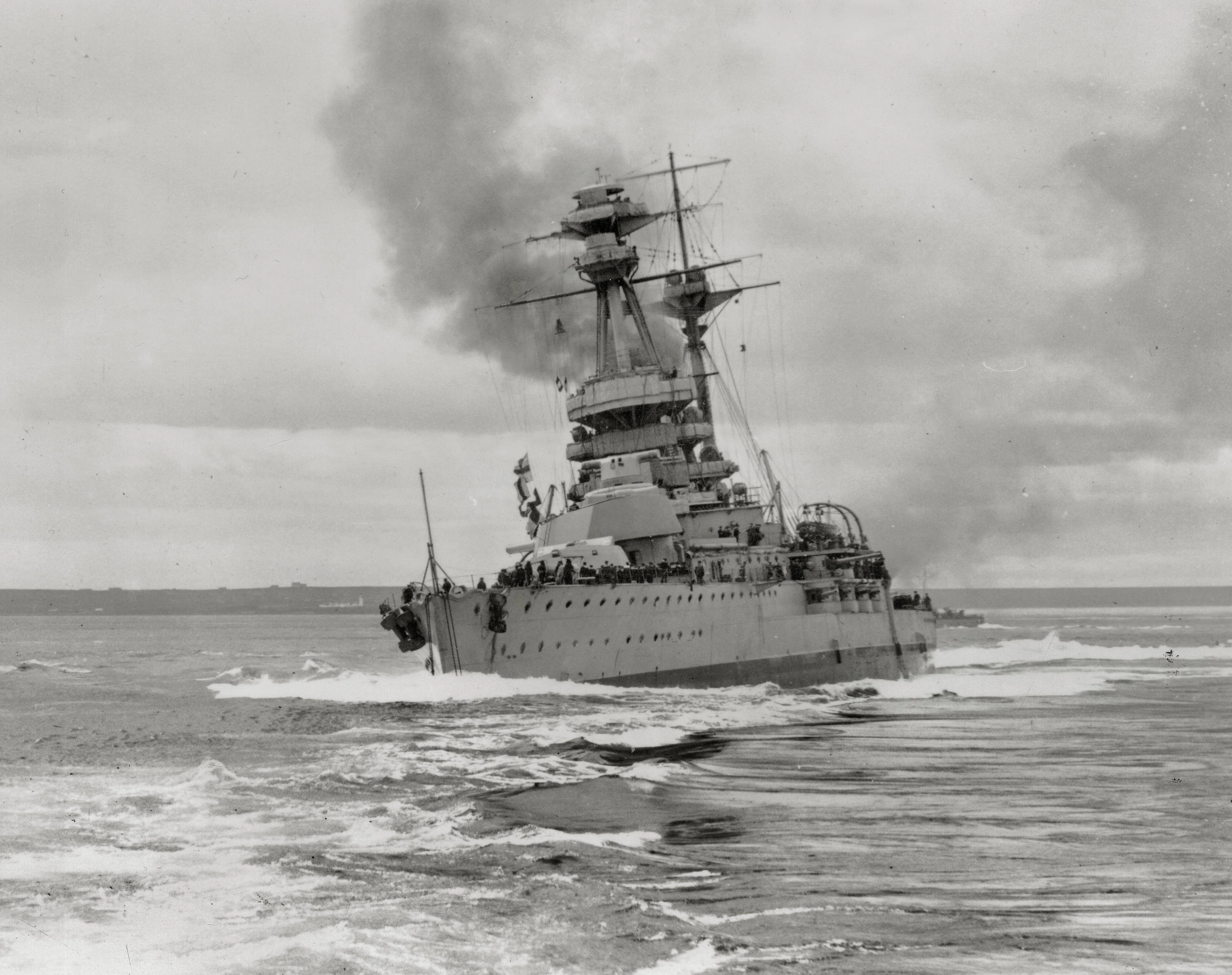
On the opposite end of the spectrum, you had Britain. The Royal Navy, with a preference for superior gunnery, tended towards lower metacentric heights. This resulted in warships with long, gentle rolling motions that made them exceptionally steady gunnery platforms. The Royal experimented with metacentric height to make even steadier warships, for instance designing the Revenge class with a metacentric height of only 3.4′ (though they realized this was too low). By World War 2, they still opted for the lower end of the spectrum with the King George V and Vanguard designs being among the lowest of their peers (7.1′ and 8.2′ respectively).
The issue got even more complicated as outside factors could influence the metacentric heights of a warship. Additional weight could detract from it while features such as hull additions or bulges could add to it. Sometimes this was done purposefully or was accepted as a consequence for other modifications. That is a topic for a future article though.
Overall, this is a very brief, very simplified description of stability and metacentric heights. If you want more technical terms or calculations, feel free to research further online. Hopefully, this answers the basic questions enough for you!
Facebook Q&A : Royal Navy BD (Between Deck) Mounts
“When reading about the Implacable class aircraft carriers, the 114mm guns are referred to as BD mounts. What does BD mean?”
Short Answer:
“BD” was a term used to designate the type of mounting, similar to how “QF” referred to a “quick firing” weapon. “BD” referred to a “between deck” mounting.
Longer, More Detailed Answer:
When most people think of a gun mount, be it open or enclosed, they think of one that is mounted atop the deck. The entire mount is visible over the deck. In the Royal Navy, such mounts were known as “UD” mounts or “Upper Deck” mounts.
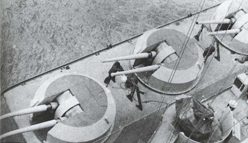
BD mounts were unique in that a portion of the mount was actually sunk under the deck. Instead of being mounted on top of a deck, the bottom of the mount was located between two of the ship’s decks, hence the “Between Deck” name.
This led to a majority of the mount being hidden under the deck, leaving only a small bit of the gun enclosure jutting above the deck. It was this portion that rose above the deck that held the guns and sighting equipment.
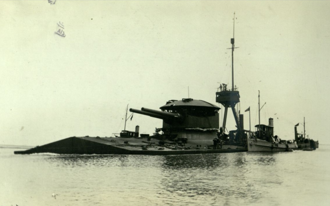
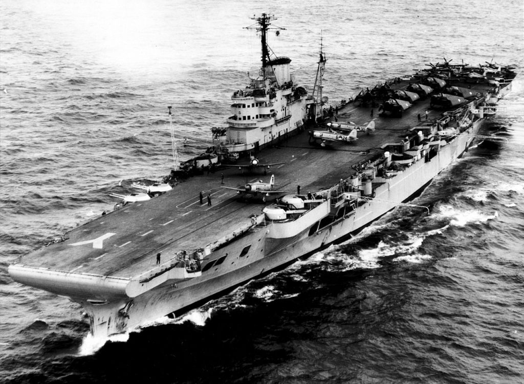
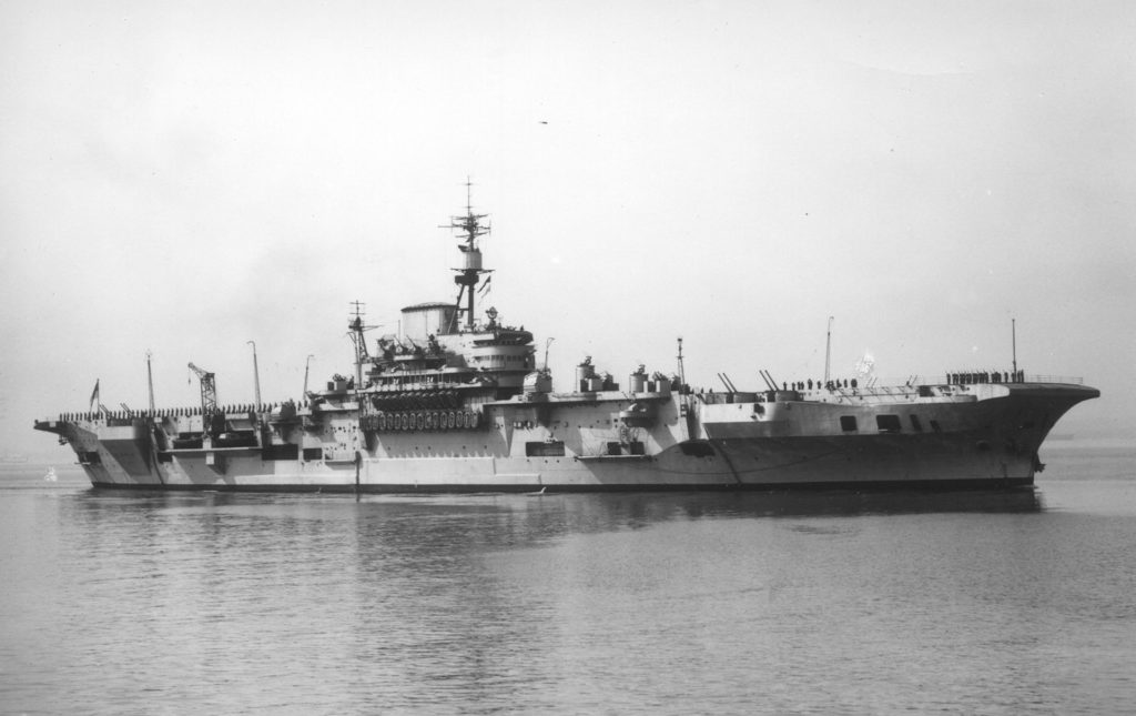
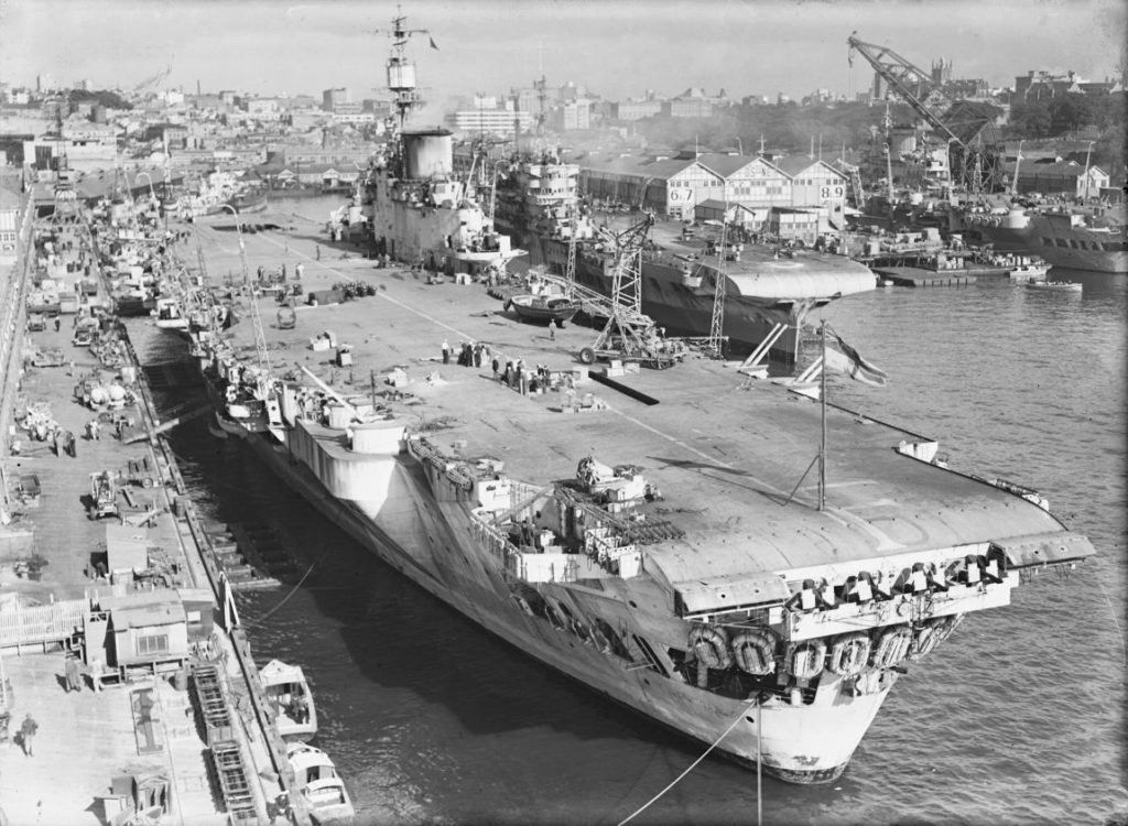
The BD mounts were used on a variety of British capital ships including their later World War 2 aircraft carriers as well as their modernized dreadnoughts (Valiant, Queen Elizabeth, and Renown).
The advantage of this arrangement was that the gun mounts were set lower in the hull, allowing the deck to provide protection for a majority of the mount. Only a small armored cover was needed. This also had the benefit of providing a slight reduction in top weight and its associated increase in stability.
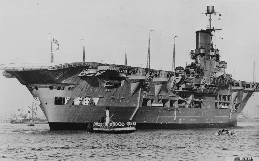
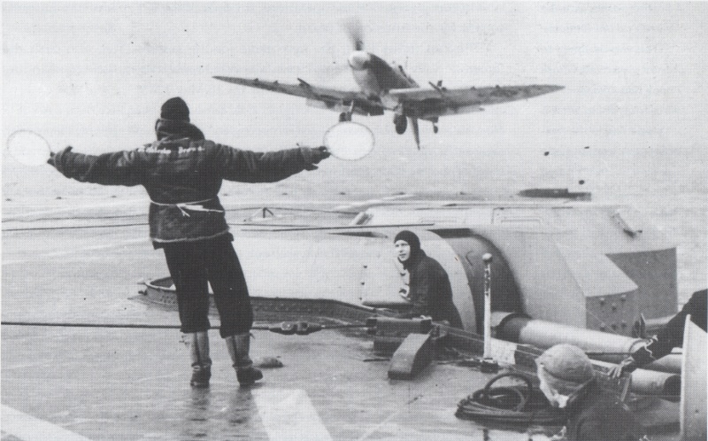
The benefit was greater for carrier installations. The lower mounts did not interfere with deck operations as much as the ones fixed to the flight deck (Think the twin 5″ guns on the Essex class). On the other hand, they still allowed the guns to fire across the flight deck, something that was impossible with mounts that were located in sponsons well below the flight deck.
We will look at these three mounts in a future post to look at the pros and cons of each style.
It’s worth pointing out that the Royal Navy tested a modified BD mount on the Implacable class carriers. This mount saw the armored roof cut shorter to allow it to sit flush with the flight deck. This further reduced interference with the flight deck and, in theory, expanded space on the flight deck.
Of course, there were drawbacks to the BD mount as well. Due to the location, maintenance of the mounts was somewhat more difficult. Accessing some components was difficult for the crew due to a lack of working room around the lower mount.
The BD mounts were also more cramped inside. The gun crews had less working room compared to roomier UD mounts. This led to a reduction in rate of fire, an important attribute effective for anti-aircraft fire.
For reasons such as this, BD mounts were generally phased out as newer, more advanced 4.5″ guns entered service. Post-War British carriers carried the latest 4.5″ guns, fitted things such as RPC equipment and automatic rammers, in UD mounts as they offered more space to house them.
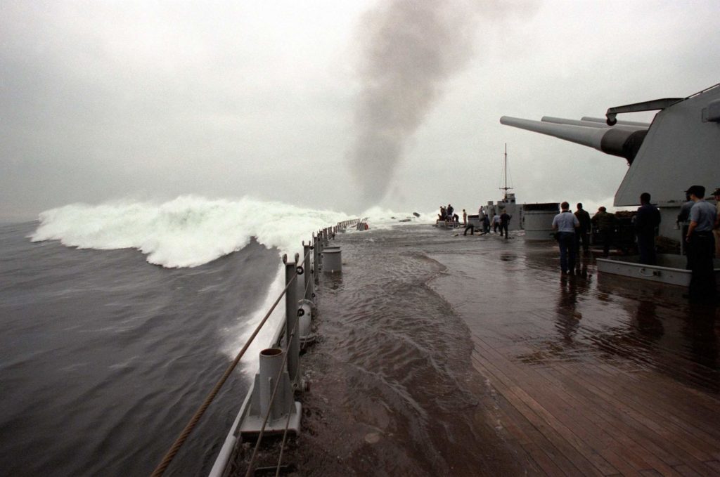
Facebook Q&A: Forcing the Engines
The battleship USS Iowa conducting a high-speed run in November 1985. The dreadnought’s roostertail and wake is churning up so much water that it’s spilling onto the deck.
I was asked about the terms “forcing the engines” and “engine overload” recently so I thought they would be good terms to tackle in a Q & A Session!
First up, engine overload.
This term was new to me, but I believe the person who asked was confusing the term “engine overload” with “design overload”.
Design overload is a feature in warship design (and most normal ships as well) where the powerplant was intentionally designed with greater power capabilities than what it is officially rated at. For instance, during the Second World War, most United States Navy warships were capable of generating about 10-25% over their rated shaft horsepower.
This feature was to provide emergency speed, something most people have equated to a time of maximum speed boost. However, this feature was largely intended to come into play should the warship lose some of its propulsion capability (screw, shaft, boilers, turbines, etc). Using design overload, the ship could increase power to the other shaft(s) to help preserve combat speed.
I haven’t seen concrete evidence, but I also imagine that design overload also bestowed a larger margin of reliability on the power plant. This is due to the fact that the powerplant would be safely operating below its designed “red line”.
However, you can exceed this red line briefly too, by forcing the engines.
Forcing the Engines
Forcing the engines simply means forcing the engines to perform over their design specifications. Unlike design overload which had a safe operating area, forcing the engines pushed them over their capabilities and into the unknown. The amount of power that the powerplant might produce was largely dependent on how much it could take and for how long.
Perhaps the most notable instance of forcing the engines took place during the Battle of Samar. During that melee, the destroyer escort Samuel B. Roberts forced her engines to increase speed. The John C. Butler class (to which the Roberts belonged) were designed to reach 24 knots at 600psi. During the Battle of Samar, Samuel B. Roberts diverted all available steam to the turbines, producing some 660psi and reportedly exceeding 28 knots.
Unlike design overload, forcing the engines would cause damage to them. So it was only intended for the direst of circumstances. So while many warships conducted speed trials where they underwent design overload, very few (if any) warships ever attempted to force the engines during trials.
A few examples of design overload:
Richelieu Class:
Rated Power: 155,000SHP / Design Overload: 179,000SHP
Iowa Class:
Rated Power: 212,000SHP / Design Overload: 254,000SHP
King George V Class:
Rated Power: 110,000SHP / Design Overload: 125,000SHP
**Though designed for 125,000SHP, the KGV class reached almost 135,000SHP during overload**
Yamato Class:
Rated Power: 150,000SHP / Design Overload: 165,000SHP
**Records were destroyed, but some sources state that Yamato generated even greater power during overload**
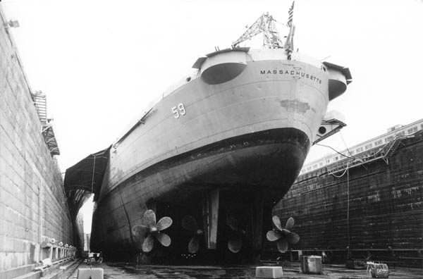
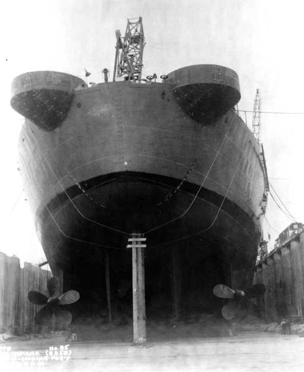
Facebook Q&A : Optimal Number of Blades on a Ship Screw
“Why didn’t more battleships use four or five-blade screws like newer ships during WW2? Would that increase their speed?”
Now this question pops up from time to time. It’s actually a pretty technical one that even I do not fully understand. However, I can break down the basics for you.
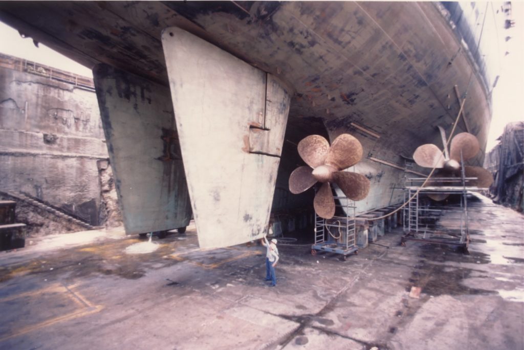
First and foremost, having more blades on a screw does not equal greater speed. In fact, it’s the exact opposite.
For the most part, the fewer blades a screw has, the more efficient it is. A single large blade pushes water more efficiently than multiple smaller blades at speed. This is due to a variety of reasons but we will focus on the biggest two:
1 – They tend to interact better with the water flowing around them. This touches on the subject of cavitation which is a subject of an article itself.
2 – Screws with fewer blades are easier to turn by the powerplant as they produce less drag. This means they require less power.
For instance, if a ship operated most efficiently with three-blade screws, replacing them with four-blade models would actually hurt performance. The additional weight and drag would actually sap some of the ship’s power.
This isn’t to say that a higher number of blades has no benefits. In fact, they do offer some benefits including:
1 – Greater initial thrust. Initial acceleration can be better due to the additional blades “biting” a great amount of water. However, this is at the cost of top speed for the reasons we have seen above.
2 – They allowed for more powerful propulsion systems. While multiple blades were heavier and had greater drag, this could be offset by more powerful machinery driving them. This additional power ignores some of the design limitations.
3 – Depending on the application, some screws with multiple blades can have reduced propeller arcs (resulting in a smaller size) compared to a similar screw with fewer blades. However, this benefit is specific to only certain instances/designs.
All of this information taken together means that the ideal number of blades on a screw is actually dependent on external factors more so than the screw itself. The warship’s design speed, powerplant, hull size, intended role, and its influence on operating RPMS (a merchant ship operating at 15 knots almost all the time vs a destroyer which would be changing speed and direction almost constantly), weight, propeller clearance requirements, and more are what dictates the optimal number of blades.
It’s finding the optimal balance between efficiency (fewer blades) and thrust (more blades).
So why did newer battleships have more blades per screw?
In this situation, you are probably thinking of instances where battleships were refitted with screws featuring more blades:
– The North Carolina class replacing their three-blade screws for four and five-blade models.
– The South Dakota class experimenting with three, four, and five-blade screw arrangements throughout the war.
– HMS Vanguard replacing her inner screws of three blades for five-blade models.
This had little to do with speed or efficiency. Instead, the changes here were almost entirely the result of vibration issues.
As the blades on the screw push through the water, they produce a powerful pressure wave. This wave travels through the water and slams into the hull, leading to vibrations that can be felt. These vibrations can be so strong that they can actually interfere with operations on the ship, most notably that of the fire control systems and general crew comfort.
Screws with fewer, though larger blades produce larger pressure waves, resulting in greater vibration problems. Designers attempted to remedy this by replacing the screws with models featuring more blades. While the screws with more blades still produced pressure waves, the number of pressure waves was increased while the individual strength of each wave was reduced.
This means that the screws with a greater number of blades operated more smoothly!
However, this was not a clear remedy. It could actually cost speed and performance, but the reduction in vibration was seen as worthwhile.
Also it’s worth pointing out that the manner in which the pressure waves interacted with the hull was also dependent on factors including screw location, shaft length, hull form, screw brackets, the use of skegs, and so on. Certain ships might benefit from more blades on the outer shafts while the inner shafts were better served by fewer blades. The opposite could be true.
Sometimes the problems were such that the issue could not be resolved at all. While the South Dakota class saw significant success in reducing vibrational issues, the problems remained persistent in the North Carolina class and on HMS Vanguard. They continued to suffer from vibrational issues throughout their careers to varying degrees.
Overall, it was an imprecise science that required much experimentation.
Have Naval History Questions you would like to ask?
Have a question that hasn’t been asked yet? Feel free to reach out and ask!
I believe that there is no such thing as a stupid question. If you have a question, please do not hesitate to reach out and ask. If I cannot answer it, I know plenty of people who can! You can ask in the comment section below or reach out to us on the various Navy General Board social media platforms.
Other Links and Interesting Reading
Want to follow Navy General Board on Social Media? Check us out on the platforms below!
Help the Website grow by purchasing a Navy General Board Shirt!
- YouTube
- The Navy General Board Forum
- Want to help the site continue to expand? Support us on Patreon.
- Learn more about how NGB got started!
More Great Articles
Check out our collection of articles. Some of our latest articles include:

Recent Comments